这里提到的LED彩色点阵屏是由一个或者多个LED彩色单元板,这种单元板没有驱动电路,需要外接相关的控制卡。对于单色或者是双色LED点阵屏/单元板,只需要使用基于STM32 MCU的控制卡。但是对于彩色单元板或者是想对单色/双色单元板实现灰阶效果,那么就需要基于FPGA/CPLD芯片的控制卡。
- 关于rpi-rgb-led-matrix
而由Henner Zeller开发的rpi-rgb-led-matrix却是可以通过树莓派来控制LED彩色单元板(https://github.com/hzeller/rpi-rgb-led-matrix/blob/master/README.md):
Controlling RGB LED display with Raspberry Pi GPIO
A library to control commonly available 32×32 or 16×32 RGB LED panels with the Raspberry Pi. Can support PWM up to 11Bit per channel, providing true 24bpp color with CIE1931 profile.
Supports 3 chains with many 32×32-panels each. On a Raspberry Pi 2, you can easily chain 12 panels in that chain (so 36 panels total), but you can stretch that to up to 96-ish panels (32 chain length) and still reach around 100Hz refresh rate with full 24Bit color (theoretical – never tested this; there might likely be timing problems with the panels that will creep up then). With fewer colors you can control even more, faster.
The LED-matrix library is (c) Henner Zeller h.zeller@acm.org with GNU General Public License Version 2.0 http://www.gnu.org/licenses/gpl-2.0.txt
The demo-main.cc example code using this library is released to the public domain.
显示屏更新的代码在这里:https://github.com/hzeller/rpi-rgb-led-matrix/blob/master/lib/framebuffer.cc:
void Framebuffer::DumpToMatrix(GPIO *io) {
  IoBits color_clk_mask;   // Mask of bits we need to set while clocking in.
  color_clk_mask.bits.p0_r1
    = color_clk_mask.bits.p0_g1
    = color_clk_mask.bits.p0_b1
    = color_clk_mask.bits.p0_r2
    = color_clk_mask.bits.p0_g2
    = color_clk_mask.bits.p0_b2 = 1;

#ifndef ONLY_SINGLE_CHAIN
  if (parallel_ >= 2) {
    color_clk_mask.bits.p1_r1
      = color_clk_mask.bits.p1_g1
      = color_clk_mask.bits.p1_b1
      = color_clk_mask.bits.p1_r2
      = color_clk_mask.bits.p1_g2
      = color_clk_mask.bits.p1_b2 = 1;
  }

  if (parallel_ >= 3) {
    color_clk_mask.bits.p2_r1
      = color_clk_mask.bits.p2_g1
      = color_clk_mask.bits.p2_b1
      = color_clk_mask.bits.p2_r2
      = color_clk_mask.bits.p2_g2
      = color_clk_mask.bits.p2_b2 = 1;
  }
#endif

#ifdef PI_REV1_RGB_PINOUT_
  color_clk_mask.bits.clock_rev1 = color_clk_mask.bits.clock_rev2 = 1;
#endif
  color_clk_mask.bits.clock = 1;

  IoBits row_mask;
  row_mask.bits.a = row_mask.bits.b = row_mask.bits.c
    = row_mask.bits.d = row_mask.bits.e = 1;

  IoBits clock, strobe, row_address;
#ifdef PI_REV1_RGB_PINOUT_
  clock.bits.clock_rev1 = clock.bits.clock_rev2 = 1;
#endif
  clock.bits.clock = 1;
  strobe.bits.strobe = 1;

  const int pwm_to_show = pwm_bits_;  // Local copy, might change in process.
  for (uint8_t d_row = 0; d_row < double_rows_; ++d_row) {
    row_address.bits.a = d_row;
    row_address.bits.b = d_row >> 1;
    row_address.bits.c = d_row >> 2;
    row_address.bits.d = d_row >> 3;
    row_address.bits.e = d_row >> 4;

    io->WriteMaskedBits(row_address.raw, row_mask.raw);  // Set row address

    // Rows can't be switched very quickly without ghosting, so we do the
    // full PWM of one row before switching rows.
    for (int b = kBitPlanes - pwm_to_show; b < kBitPlanes; ++b) {
      IoBits *row_data = ValueAt(d_row, 0, b);
      // While the output enable is still on, we can already clock in the next
      // data.
      for (int col = 0; col < columns_; ++col) {
        const IoBits &out = *row_data++;
        io->WriteMaskedBits(out.raw, color_clk_mask.raw);  // col + reset clock
        io->SetBits(clock.raw);               // Rising edge: clock color in.
      }
      io->ClearBits(color_clk_mask.raw);    // clock back to normal.

      // OE of the previous row-data must be finished before strobe.
      sOutputEnablePulser->WaitPulseFinished();

      io->SetBits(strobe.raw);   // Strobe in the previously clocked in row.
      io->ClearBits(strobe.raw);

      // Now switch on for the sleep time necessary for that bit-plane.
      sOutputEnablePulser->SendPulse(b);
    }
    sOutputEnablePulser->WaitPulseFinished();
  }
}
从这里可以看到,对于显示屏中的每一行,先做11位的PWM控制,做完之后,再更新下一行。由于在PWM更新时,最短一次可能只需要100ns, 所以想使用STM32实现这样的效果根本是不可能的。(假设STM32核心频率为72MHz, 执行一条指令需要0.000,000,0139s = 13.9ns,同时可以看出这种方式需要的内存也是很大的,对于32×32 x rgb的单元板,光显示就需要32 * 32 * 3 * 11/8 = 4224 byte, 也许今后可以试试使用4/5位的PWM控制)。
NOTE:
使用硬件PWM是为了提供精确的控制时间。
- 使用16MHz Arduion Uno进行控制
哎,神人啊!!
Keep in mind that these displays are normally designed to be driven by FPGAs or other high speed processors; they do not have built in PWM control of any kind. Instead, you’re supposed to redraw the screen over and over to ‘manually’ PWM the whole thing. On a 16 MHz Arduino Uno, we managed to squeeze 12-bit color (4096 colors) but this display would really shine if driven by an FPGA, CPLD, Propeller, XMOS or other high speed multi-processor controller.
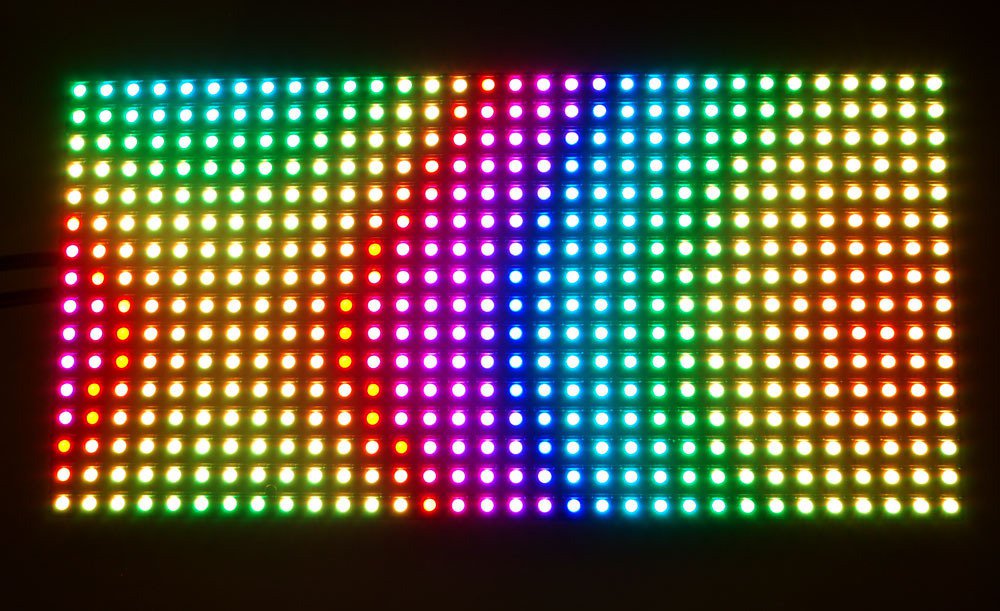
(图片来自:https://learn.adafruit.com/assets/2937)
- 相关的参考文档:
- https://github.com/hzeller/rpi-rgb-led-matrix
- https://learn.adafruit.com/32×16-32×32-rgb-led-matrix/overview