ST官方提供了ST-LINK/V2-1调试器的原理图,PCB图及相关的固件更新工具(Stlink Utility或者ST-LINK firmware upgrade)当然也可以通过第三方的工具对调试器进行固件的升级操作(STLinkReflash)。但如果你在使用ST-LINK/V2-1的过程中不慎将原有的固件破环或者是MCU烧毁,使得ST-LINK/V2-1无法正常使用,这时候你就需要一个可用的bootloader进行修复。
- -实现一个简单的bootloader, 能够实现固件的下载及加载
经过进一个月的分析,不断尝试,自己写一个bootloader实现固件下载更新及加载也是可能的。
完整的固件包含如下这几个部分:
| Flash size: 128KiB | ||||
| bootloader: 15KiB | system parameter: 1KiB | firmware: 111KiB | manifest: 1KiB | |
- -了解固件升级相关的通信协议
由于STLinkReflash命令在固件升级过程中,可以显示升级过程中发送及接收的数据的相关内容,并且结合OpenOCD源代码中关于ST-LINK通信相关的代码,可以很容易地猜测出固件升级的流程:
NOTE:
STLinkReflash工具在写入ST-LINK/V2-1的时候,没有去更新固件的配置信息(位于flash 0x08003c00 ~ 0x08003ffff)。这使得如果bootloader不包启配置信息(只包含flash前15KiB的数据),那么通过该工具写入的ST-LINK/V2-1固件是无法使用的(USB无法正常枚举),而必须先通过STLink Utility工具进行固件更新。
加密算法,通过分析STLinkReflash工具,我们知道固件在传送过程中,会进行加密,我们需要相关的加密算法来实现:
- - 官方原版bootloader
有了固件升级相关的通信协议及相关的参考文档,获取官方的bootloader也不是什么难事。
原以为有了ST-LINK/V2-1的固件并且知道固件的起始地址,就可以写一个简单的bootloader加载固件,可事实并非如此(加载JLink固件可以正常运行,但是对于ST-LINK/V2-1的固件,就没有那么走运了),还是需要分析调试bootloader代码,以发现其中的差异:
- - USB接口实现及其配置
ST-LINK/V2-1通过USB接口与PC机进行通信,在bootloader模式下接口的相关配置信息在linux/ubuntu下可通过lsusb命令查看:
$ lsusb -d 0483: -v

Bus 001 Device 014: ID 0483:3748 STMicroelectronics ST-LINK/V2
Couldn't open device, some information will be missing
Device Descriptor:
  bLength                18
  bDescriptorType         1
  bcdUSB               2.00
  bDeviceClass            0 (Defined at Interface level)
  bDeviceSubClass         0
  bDeviceProtocol         0
  bMaxPacketSize0        64
  idVendor           0x0483 STMicroelectronics
  idProduct          0x3748 ST-LINK/V2
  bcdDevice            1.00
  iManufacturer           1
  iProduct                2
  iSerial                 3
  bNumConfigurations      1
  Configuration Descriptor:
    bLength                 9
    bDescriptorType         2
    wTotalLength           39
    bNumInterfaces          1
    bConfigurationValue     1
    iConfiguration          0
    bmAttributes         0x80
      (Bus Powered)
    MaxPower              100mA
    Interface Descriptor:
      bLength                 9
      bDescriptorType         4
      bInterfaceNumber        0
      bAlternateSetting       0
      bNumEndpoints           3
      bInterfaceClass       255 Vendor Specific Class
      bInterfaceSubClass    255 Vendor Specific Subclass
      bInterfaceProtocol    255 Vendor Specific Protocol
      iInterface              4
      Endpoint Descriptor:
        bLength                 7
        bDescriptorType         5
        bEndpointAddress     0x81  EP 1 IN
        bmAttributes            2
          Transfer Type            Bulk
          Synch Type               None
          Usage Type               Data
        wMaxPacketSize     0x0040  1x 64 bytes
        bInterval               0
      Endpoint Descriptor:
        bLength                 7
        bDescriptorType         5
        bEndpointAddress     0x02  EP 2 OUT
        bmAttributes            2
          Transfer Type            Bulk
          Synch Type               None
          Usage Type               Data
        wMaxPacketSize     0x0040  1x 64 bytes
        bInterval               0
      Endpoint Descriptor:
        bLength                 7
        bDescriptorType         5
        bEndpointAddress     0x83  EP 3 IN
        bmAttributes            2
          Transfer Type            Bulk
          Synch Type               None
          Usage Type               Data
        wMaxPacketSize     0x0040  1x 64 bytes
        bInterval               0
有了这些相关信息,我们就可以完成USB接口配置的相关代码了。这里我们会用到EP 1 IN 与 EP 2 OUT而EP 3 IN在ST-LINK进行debug/trace的时候会用到。
- -基于ChibiOS/RT v16.1.2的实时系统实现的bootloader
1. 系统上电之后会检查固件是否完整,固件完整则跳转执行固件代码否则进入DFU模式:
/*
 * Application entry point.
 */
int __attribute__((noreturn)) main(void) {
  /*
   * System initializations.
   * - HAL initialization, this also initializes the configured device drivers
   *   and performs the board-specific initializations.
   */
  halInit();

  do {
    uint32_t flashSize, magicValue;

    /* Check the firmware intergrity */
    flashSize = (*(volatile uint32_t *)0x1FFFF7E0 & 0xffff) << 10;
    /* Magic value locate at the last 4 bytes in the flash */
    magicValue = *(volatile uint32_t *)(flashSize - 4);
    if (magicValue != 0xa50027d3) {
        break;
    }

    /* Check power on reason */
    if ((RCC->CSR & RCC_CSR_SFTRSTF) != 0 && BKP->DR1 != 0xfeed) {
        /* Software reset occurred */
        break;
    }

    if (BKP->DR1 == 0xfeed) BKP->DR1 = 0x0000;

    /* Clear reset flag */
    RCC->CSR |= RCC_CSR_RMVF;

    JumpToUserApp(0x08004000);
  } while (0);

  /*
   * System initializations.
   * - Kernel initialization, the main() function becomes a thread and the
   *   RTOS is active.
   */
  chSysInit();

  // ...
}
NOTE:
这里可以看到固件检查及跳转是在halInit()之后及chSysInit()之前。
2. 跳转时要重新设置线程工作模式: 在特权模式下运行并使用Main Stack:
void JumpToUserApp(uint32_t pAppAddr) {
  volatile uint32_t *pMspAddr;
  volatile uint32_t *pJmpAddr;

  /* Get main stack address from the application vector table */
  pMspAddr = (volatile uint32_t *)(pAppAddr + 0);
  /* Get jump address from application vector table */
  pJmpAddr = (volatile uint32_t *)(pAppAddr + 4);

  /* Set stack pointer as in application's vector table */
  __set_MSP(*pMspAddr);

  /* Privileged and using main stack */
  __set_CONTROL(0);

  /* Jump to the new application */
  (*(void (*)(void))*pJmpAddr)();
}
NOTE:
ChibiOS/RT初始化时,会使MCU工作在特权模式下,但使用的stack为thread stack。相关的代码在:os/common/ports/ARMCMx/compilers/GCC/crt0_v7m.s
/**
 * @brief   Control special register initialization value.
 * @details The system is setup to run in privileged mode using the PSP
 *          stack (dual stack mode).
 */
#if !defined(CRT0_CONTROL_INIT) || defined(__DOXYGEN__)
#define CRT0_CONTROL_INIT                   (CONTROL_USE_PSP |              \
                                             CONTROL_MODE_PRIVILEGED)
#endif

// ...
Reset_Handler:
                /* Interrupts are globally masked initially.*/
                cpsid   i

                /* PSP stack pointers initialization.*/
                ldr     r0, =__process_stack_end__
                msr     PSP, r0

#if CRT0_INIT_FPU == TRUE
                /* FPU FPCCR initialization.*/
                movw    r0, #CRT0_FPCCR_INIT & 0xFFFF
                movt    r0, #CRT0_FPCCR_INIT >> 16
                movw    r1, #SCB_FPCCR & 0xFFFF
                movt    r1, #SCB_FPCCR >> 16
                str     r0, [r1]
                dsb
                isb

                /* CPACR initialization.*/
                movw    r0, #CRT0_CPACR_INIT & 0xFFFF
                movt    r0, #CRT0_CPACR_INIT >> 16
                movw    r1, #SCB_CPACR & 0xFFFF
                movt    r1, #SCB_CPACR >> 16
                str     r0, [r1]
                dsb
                isb

                /* FPU FPSCR initially cleared.*/
                mov     r0, #0
                vmsr    FPSCR, r0

                /* FPU FPDSCR initially cleared.*/
                movw    r1, #SCB_FPDSCR & 0xFFFF
                movt    r1, #SCB_FPDSCR >> 16
                str     r0, [r1]

                /* Enforcing FPCA bit in the CONTROL register.*/
                movs    r0, #CRT0_CONTROL_INIT | CONTROL_FPCA

#else
                movs    r0, #CRT0_CONTROL_INIT
#endif

                /* CONTROL register initialization as configured.*/
                msr     CONTROL, r0
                isb
// ...
- -相关源代码
这里提供部分代码供参考:
https://github.com/brobwind/chibios_bro_dbg_link_v2_1
- -预编译固件及己知问题
相关的固件可以从这里下载:2016_11_24_BRO-DBG-LINK-V2-1_BL-20161121.bin
己知问题:
- 下载ST-LINK/V2-1固件之后,无法再通过Stlink Utility,STLink firmware upgrade和STLinkReflash工具更新固件。
NOTE:
设置volume label可以通过ST-LINK firmware upgrade工具完成,label的最大长度为11字节。
ST-LINK firmware upgrade工具还可以指定固件类型:
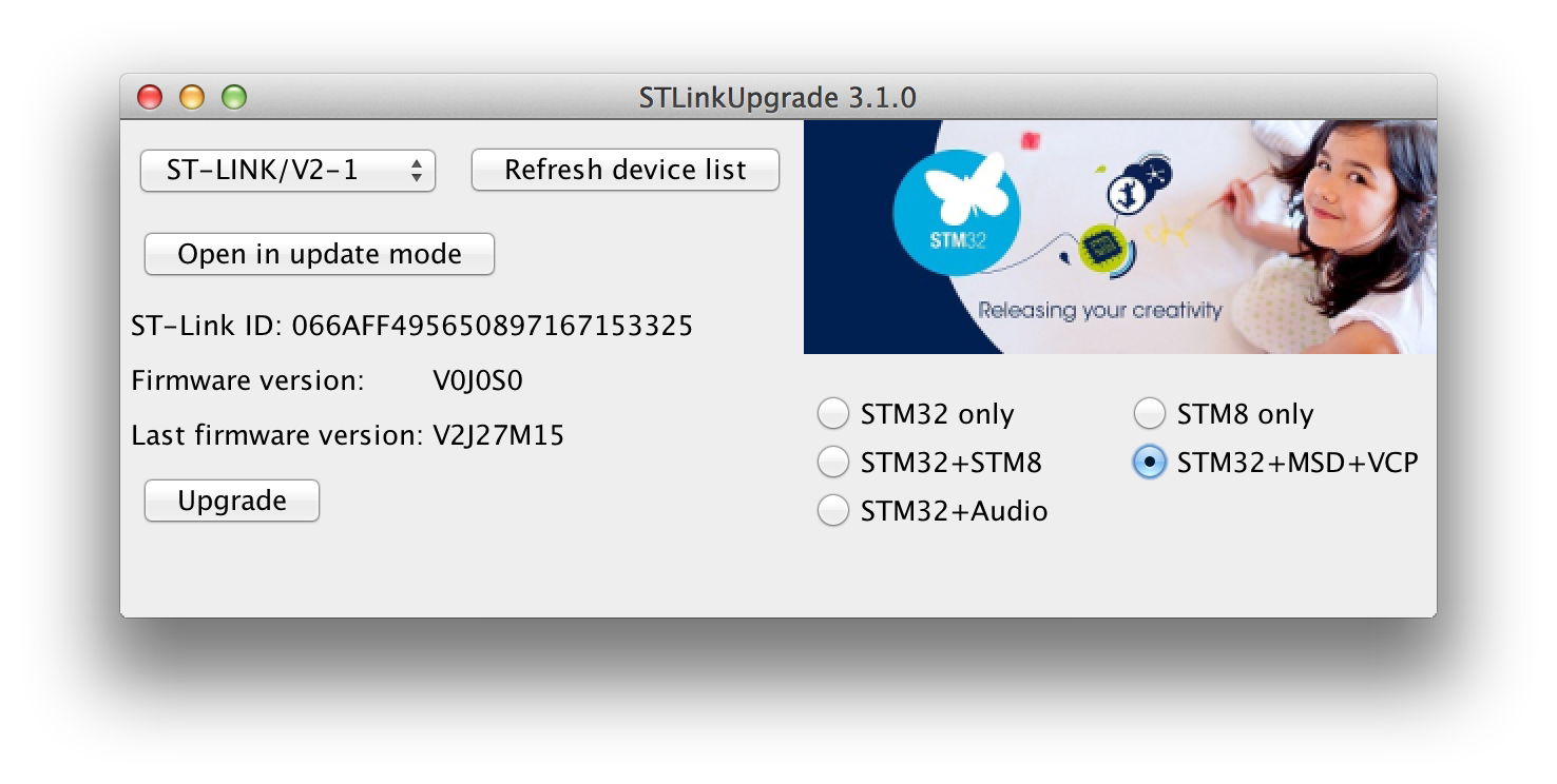
- 相关的参考文档
- http://www.chibios.org/dokuwiki/doku.php
- http://www.st.com/zh/embedded-software/stsw-link007.html
- http://infocenter.arm.com/help/topic/com.arm.doc.dai0179b/ar01s02s06.html