- 硬件配置
40pin head的引脚定义如下(图片来自http://elinux.org/RPi_Low-level_peripherals#P5_header):
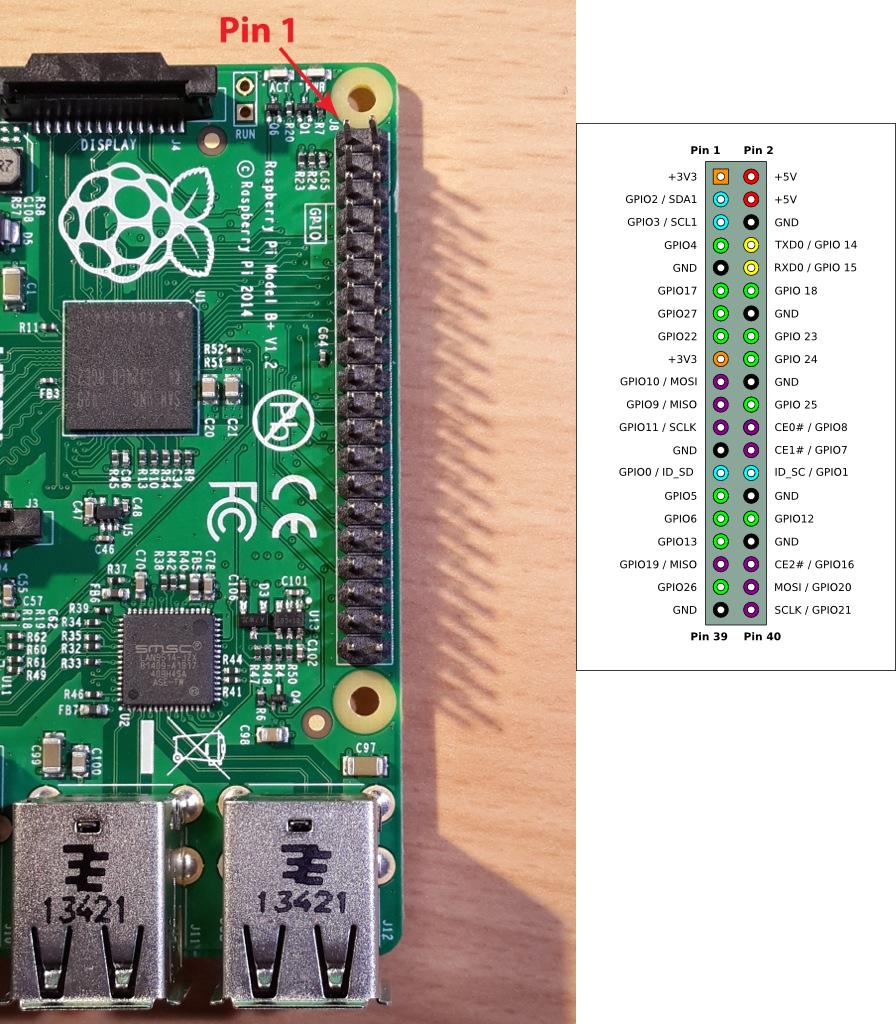
再看看hardware/bsp/kernel/hzak/rpi-4.1.y/arch/arm/boot/dts/bcm2709-rpi-2-b.dts文件,各功能模块使用的GPIO如下:
- sdhost: 48, 49, 50, 51, 52, 53
- spi0: 7, 8, 9, 10, 11
- i2c0: 0, 1
- i2c1(CSI): 2, 3
- i2s: 18, 19, 20, 21
- uart0: 14, 15 (kernel log)
- SD card access indicator: 16
最后就剩下了:4, 17, 27(CSI), 22, 23, 24, 25, 5(CSI), 6(LAN_RUN), 12, 13, 26
为了方便接线,选择靠近GND的几个pin, GPIO与LED的对应关系如下:
- GPIO23 -> LED1
- GPIO24 -> LED2
- GPIO12 -> LED3
- GPIO26 -> LED4
[2016-02-29 21:56:24]
在brillo-m10-dev分支上继续->@<-
NOTE:
1. 在选择Pin脚的时候还应该注意不要选择Pin27 (ID_SD)和Pin 28 (ID_SC):
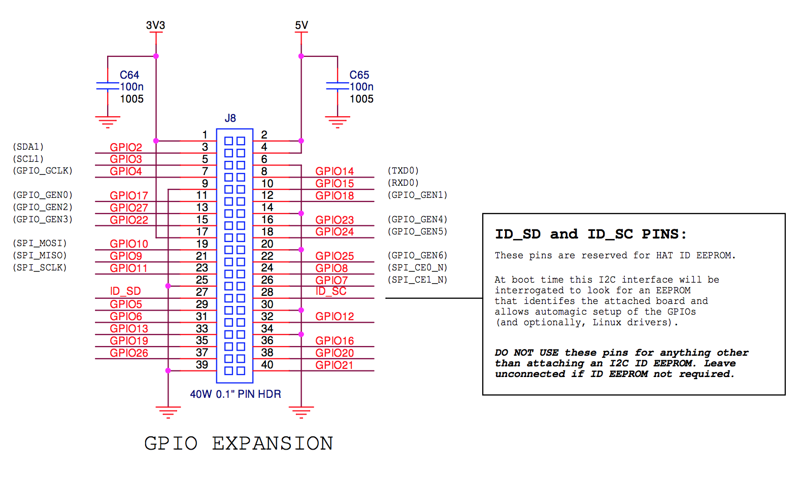
2. 原来RPi只是开源了软件部份,硬件是不开源的,所以在官网release出来的电路图是不完整的:
https://github.com/raspberrypi/documentation/issues/347#issuecomment-221855398
Raspberry Pi has never been open hardware. All our software is open source, and we release as much of the hardware schematics as we can.
- 参考文档:
- https://learn.adafruit.com/connecting-a-16×32-rgb-led-matrix-panel-to-a-raspberry-pi
- https://github.com/hzeller/rpi-rgb-led-matrix
- https://github.com/Boomerific/rpi-rgb-led-matrix
- https://github.com/raspberrypi/documentation/blob/master/hardware/raspberrypi/schematics/RPI-3B-V1_2-SCHEMATIC-REDUCED.pdf