最近买了一些步进电机,同时也买了一些步进电机驱动板。步进电机驱动板使用的是TI公司的DRV8825芯片,控制步进电机的速度是通过一系列的脉冲信号,所以需要STM32F030F4P6能够输出方波。
DRV8825芯片的数据手册请看这里:http://www.ti.com/lit/ds/slvsa73f/slvsa73f.pdf
- 关于DRV8825模块
1. DRV8825模块实物图(图片来自http://fritzing.org/projects/drv-8825-stepper-motor-carrier-high-current):
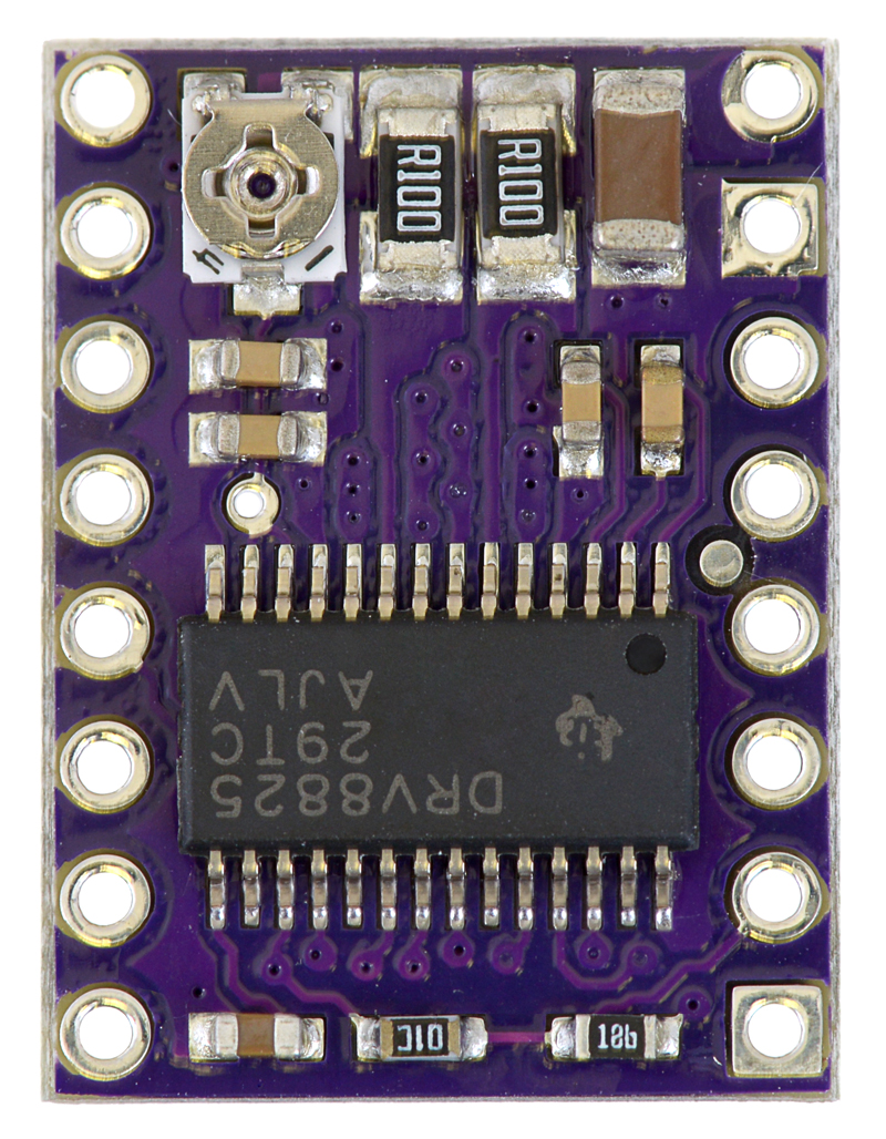
相关的文档请看这里:https://www.pololu.com/product/2133
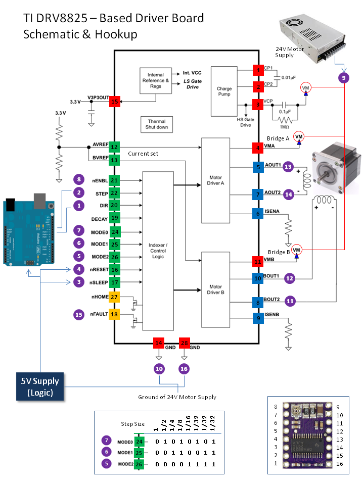
2. DRV8825模块原理图(图片来自http://fritzing.org/projects/drv-8825-stepper-motor-carrier-high-current):
- 步进电机
使用42步进电机,具体型号为17PM-F438B, 相关的文档可以参考这里:http://www.nmbtc.com/content/pdfs/17PM-F.pdf
这里我们需要注意的是步进电机的Torque/Speed Characterisics(力矩与转动速度的关系):
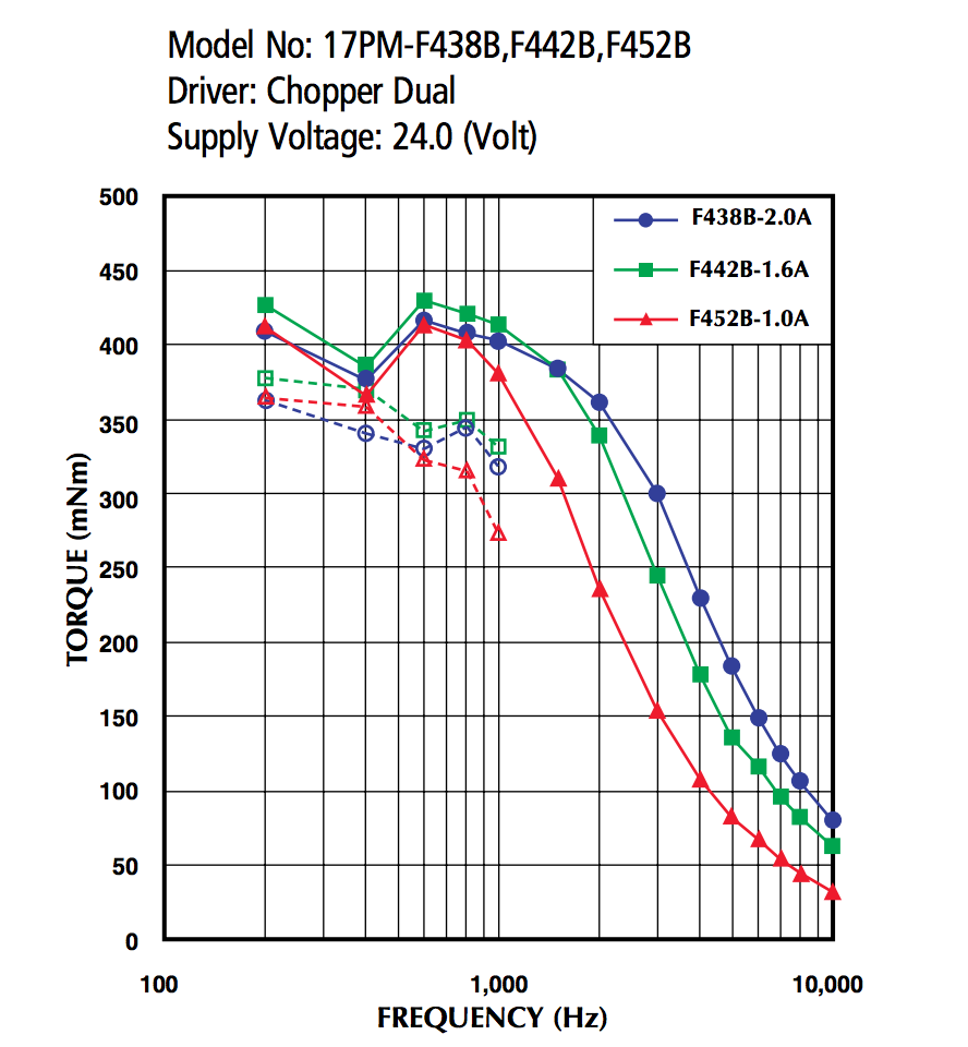
从这里我们也可以看到步进电机的供电电压为24V,脉冲频率在200~1000Hz时,电机的扭力最大。
电机启动时频率需小为1000Hz, 在运动过程中逐步增大频率,提高转数。
- 代码实现
代码基于ChibiOS/RT 16.1.x版本,需要使用到STM32F030F4P6 MCU中的一个定时器,以便能够输出较为精确的方波信号,这里使用TIM_CH3即PA10作为信号输出。
相关的代码如下:
/*
 * GPT1 configuration.
 */
static const GPTConfig gpt1cfg = {
  100000, /* 100KHz timer clock.*/ // The Max step frequency of DRV8825 is 250KHz
  NULL,    /* Timer callback.*/
  0,
  0
};

int main(void) {

  /*
   * System initializations.
   * - HAL initialization, this also initializes the configured device drivers
   *   and performs the board-specific initializations.
   * - Kernel initialization, the main() function becomes a thread and the
   *   RTOS is active.
   */
  halInit();
  chSysInit();

  palSetPadMode(GPIOA, 10, PAL_MODE_ALTERNATE(2) | PAL_STM32_OTYPE_PUSHPULL | PAL_STM32_OSPEED_HIGHEST | PAL_STM32_PUPDR_PULLUP); // PA10 - TIM1_CH3 - I2C1_SDA

  gptStart(&GPTD1, &gpt1cfg);

  uint16_t ccer, cr2, ccmr2;

  /* Disable the channel 2: Reset the CC2E Bit */
  GPTD1.tim->CCER &= (uint16_t)(~((uint16_t)TIM_CCER_CC3E));

  /* Get the TIMx CCER register value */
  ccer = GPTD1.tim->CCER;
  /* Get the TIMx CR2 register value */
  cr2 = GPTD1.tim->CR2;
  /* Get the TIMx CCMR2 register value */
  ccmr2 = GPTD1.tim->CCMR2;

  /* Reset the Output Compare mode and Capture/Compare selection Bits */
  ccmr2 &= (uint16_t)(~((uint16_t)TIM_CCMR2_OC3M));
  ccmr2 &= (uint16_t)(~((uint16_t)TIM_CCMR2_CC3S));

  /* Select the Output Compare Mode: toggle */
  ccmr2 |= TIM_CCMR2_OC3M_0 | TIM_CCMR2_OC3M_1;

  /* Reset the Output Polarity level */
  ccer &= (uint16_t)(~((uint16_t)TIM_CCER_CC3P));
  /* Set the Output State */
  ccer |= TIM_CCER_CC3E;

  /* Reset the Output N Polarity level */
  ccer &= (uint16_t)(~((uint16_t)TIM_CCER_CC3NP));
  /* Reset the Output N State */
  ccer &= (uint16_t)(~((uint16_t)TIM_CCER_CC3NE));

  /* Reset the Output Compare and Output Compare N IDLE State */
  cr2 &= (uint16_t)(~((uint16_t)TIM_CR2_OIS3));
cr2 &= (uint16_t)(~((uint16_t)TIM_CR2_OIS3N));

  /* Set the Capture Compare Register value */
  GPTD1.tim->CCR[2] = 1;

  /* Write to TIMx CR2 */
  GPTD1.tim->CR2 = cr2;
  /* Write to TIMx CCMR2 */
  GPTD1.tim->CCMR2 = ccmr2;
  /* Write to TIMx CCER */
  GPTD1.tim->CCER = ccer;

  // == Config preload ==
  ccmr2 = GPTD1.tim->CCMR2;
  /* Reset the OC3PE Bit */
  ccmr2 &= (uint16_t)~((uint16_t)TIM_CCMR2_OC3PE);
  /* Write to TIMx CCMR2 register */
  GPTD1.tim->CCMR2 = ccmr2;

  // == Enable output (MOE=1) ==
  GPTD1.tim->BDTR |= TIM_BDTR_MOE;

  // == Enable counter ==
  gptStartContinuous(&GPTD1, 2);

  // ...
}
相关的代码参考:STM32F0xx_StdPeriph_Lib_V1.5.0/Projects/STM32F0xx_StdPeriph_Examples/TIM/TIM_OCToggle/
相关的文档参考DM00091010.pdf – P382/P742:
A.8.7 Output compare configuration code example
/* (1) Set prescaler to 3, so APBCLK/4 i.e 12MHz */
/* (2) Set ARR = 12000 -1 */
/* (3) Set CCRx = ARR, as timer clock is 12MHz, an event occurs each 1 ms */ /* (4) Select toggle mode on OC1 (OC1M = 011),
       disable preload register on OC1 (OC1PE = 0, reset value) */
/* (5) Select active high polarity on OC1 (CC1P = 0, reset value),
enable the output on OC1 (CC1E = 1)*/
/* (6) Enable output (MOE = 1)*/
/* (7) Enable counter */
TIMx->PSC |= 3; /* (1) */
TIMx->ARR = 12000 - 1; /* (2) */
TIMx->CCR1 = 12000 - 1; /* (3) */
TIMx->CCMR1 |= TIM_CCMR1_OC1M_0 | TIM_CCMR1_OC1M_1; /* (4) */ TIMx->CCER |= TIM_CCER_CC1E; /* (5)*/
TIMx->BDTR |= TIM_BDTR_MOE; /* (6) */
TIMx->CR1 |= TIM_CR1_CEN; /* (7) */
NOTE:
从代码上TIM_OCToggle并没有去设置TIM的BDTR寄存器,但实际操作发现如果不去设置BDTR的值,那么PA10是无法输出方波信号的。
这里只是提供输出固定频率的方法,实际的步进电机驱动算法有待完善。
- 相关的参考文档
- http://www.ti.com/lit/ds/slvsa73f/slvsa73f.pdf
- http://fritzing.org/projects/drv-8825-stepper-motor-carrier-high-current
- http://www.nmbtc.com/content/pdfs/17PM-F.pdf
- https://www.pololu.com/product/2132
- https://www.pololu.com/product/2133