之前,我们试过使用树莓派的GPIO直接点亮LED彩色单元板:
但这种方式:
1。 太耗CPU资源了,与LED数量成正比
2。 如果更新不及时,会闪屏,影响视觉效果
3。刷新率低
看来,还是需要通过FPGA来实现一把了。
- 转接板及电平转换
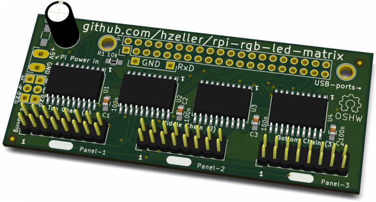
树莓派GPIO接口的电平为3.3V(https://www.raspberrypi.org/documentation/usage/gpio/), 而HUB75使用的电平为5V,需要进行电平转换。
电平转换用到的芯片是74HCT245, 将3.3v 电平转成 5 v 电平,接入彩色 LED单元板的hub75接口。
(图片来自https://github.com/hzeller/rpi-rgb-led-matrix/tree/master/adapter/active-3)
- 通信方式
目前看来,树莓派与FPGA通信,最理想的还是通过SPI,让SPI总线跑在48MHz, 理论传输速率可以达到48,000,000 / 8 = 6, 000, 000 约5.72MiB/s,而实际的传输速率可以达到4MiB/s左右。对于UART, I2C这种最大只能传输KB级的数据,高得多了。
来自:http://valentfx.com/wiki/index.php?title=LOGI_Bone_User_Manual :
Raspberry Pi SPI to FPGA Interface
The Raspberry Pi to FPGA main communication interface is the PI SPI port. The Max stable SPI clock rate that has been tested is 32-48Mhz. Based on our development experience there are some instability issues that can occur when using higher clock rates. By default the current LOGI SPI drivers runs at 48 Mhz With the current 48Mhz clock and direct communication to the FPGA the user can expect to get 4 MB/S throughput between the Raspberry Pi and the FPGA.
- 相关的参考文档
- https://www.christidis.info/index.php/personal-projects/fpga-dot-matrix-display
- https://www.open-electronics.org/a-fpga-controlled-rgb-led-matrix-for-incredible-effects-the-hardware/
- https://github.com/hzeller/rpi-rgb-led-matrix/tree/master/adapter/active-3
- http://bikerglen.com/blog/expanding-the-beaglebone-black-and-fpga-to-drive-6-or-more-panels/
